Runxin valves: reading the designation, and when manual is enough
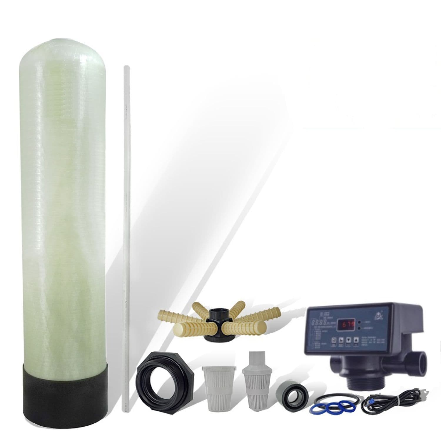
A unit in the catalogue is designated by two parts separated by a slash: 1054/F67P, 0817/F117Q3, 2472/2F56D. The first part is the tank, the second is the valve — and it is the valve that decides what the unit measures the cycle by, how much water it will pass and what the operator will have to do. Here is what the designation states unambiguously and what you still have to look up in the description of the particular version.
What the designation is made of
The first part is the tank size in inches: 0817 is 8×17″, 1054 is 10×54″, 2472 is 24×72″. The diameter governs the peak flow through the media bed, the height governs its volume.
The second part is the control valve: the letter F, the family number and an alphanumeric version index. The catalogue features the families F56, F63, F65, F67, F68, F69, F71, F74, F75, F77, F82, F96, F112, F116, F117.
The main mistake when reading these designations is to treat the family number as a size scale. It is not one. F117Q3 sits on an 8×17″ tank, while F112A3 sits on a 42×72″; F82B3 is used on tanks from 8×35″ to 18×65″. The number tells you the family, not the throughput.
Two other figures are worth checking, and both are tied to tank size. Tanks of 8 to 13 inches carry valves with 3/4 and 1 inch connections and a capacity of up to 4.5 m³/h. Tanks of 24 inches and above are fitted with larger valves, with 2 and 3 inch connections and a capacity of 10 to 50 m³/h. Between those two groups the family designation tells you nothing — go by the version instead.
A separate note is (Side) in the name: 4272/F77B1 (Side), 4872/F77A3 (Side). This is side mounting, cut into the tank wall. Everything else in the range is top mounted, with the valve screwed into the tank neck from above.
A filtration valve and a softening valve are different devices
This is the distinction that costs the most when you get it wrong. A filtration valve runs a backwash cycle of the media without any reagent: F67C, F67Q1, F71B, F75A1, F77B1. A softening valve regenerates ion exchange media with a reagent solution, which means it has an assembly for drawing solution from the brine tank and a slow rinse stage: F63C3, F69A3, F74A3, F117Q3.
That is why one and the same tank hosts two parallel ranges. On a 24×72″ tank reagent-free filtration runs on F67C, F67Q1, F75A1, F77B1, while ion exchange runs on F74A3, F74Q3, F77A3. The numbers are adjacent, the purpose is different, and you cannot fit one in place of the other: a filtration valve cannot draw brine, and its cycle does not contain the required stages.
Hence a practical rule when ordering spares and replacing parts: check not only the connection and the mounting but also the purpose — filtration or regeneration with a reagent.
The water meter: where it shows up in the designation
Ion exchange versions with a water meter are marked directly in the catalogue: F63C3, F69A3, F69P3, F74Q3, F82B3, F116Q3, F117Q3. Alongside them are versions without a meter — F63C1, F65B1, F69A1. The former count the interval between regenerations by the volume actually passed, the latter by time.
The meter has its own operational side. It does not track hardness and does not measure the resin's remaining capacity — it counts cubic metres up to the figure entered during commissioning. If that figure was picked "with a margin" instead of calculated from the water analysis, the valve will dutifully work through the volume it was given and let hard water past at the end of the cycle. Checking the outlet regularly once three quarters of the cycle have run is the cheapest diagnostic there is.
Second: the meter sits in the water path. Suspended solids and oxidised iron that reach the valve settle on its impeller, and the count starts to read low. That is one more argument for mechanical pretreatment ahead of the unit — not for the sake of the resin, but for the sake of the controls.
The manual valve: where it still makes sense
Manual versions in the catalogue are gathered in the F56 family. F56E and F56A sit on tanks from 8×17″ to 21×62″, 2F56D on large ones, from 21×62″ to 42×72″. The smallest version, 0817/F56E, is rated up to 2 m³/h with a 3/4″ connection.
The filter layout itself is the same as in automatic units: a fibreglass tank with polyethylene lamination, granular media, a supporting gravel layer, a drain and distribution system. Iron and manganese oxidise on the media, are retained within its depth and go to drain during backwash. The only difference is the control: backwash is started and switched over by the operator.
Two consequences follow at once. The unit does not depend on mains power and has no electronics to lose in a voltage surge. And it demands a routine: the backwash frequency is set by the combined content of iron, manganese and hydrogen sulphide in the raw water, and the backwashes themselves have to be run by a person, not a timer.
| Manual valve (F56E, F56A, 2F56D) | Automatic valve | |
|---|---|---|
| Backwash start | manually by the operator | by time or by meter |
| Power supply | not required | required |
| What happens without attention | the media silts up, differential pressure grows | the cycle runs to program |
| Who it suits | a site with staff on duty, a seasonal house, a standby train | a site without a permanent operator |
| Where it fails | an unmanned site, night and shift water draw | a site with unstable power and no stabiliser |
A manual valve is guaranteed to fail in three cases: there is nobody on site to start the backwash on the right day; water is needed round the clock while backwash requires taking the filter out of service; the iron content is higher than calculated and the interval between backwashes shortens faster than the routine can react. In any of these, saving on automation ends in replacing the media.
Mounting, drain and service
Top mounting requires clearance above the tank: the valve is removed as a whole to reach the upper distributor and the media. For tanks such as 14×65″ and 18×65″ this is a noticeable figure, and it is designed into the room rather than discovered at the first service.
Side mounting on large tanks solves the height question but shifts the load onto the pipework: the valve is cut into the wall, and the pipes must have supports of their own instead of hanging on the connection.
The drain is the second figure most often underestimated. Backwash runs at a flow higher than the service flow, and the drain line has to take it. A filter also needs a reserve of water for the backwash itself: if the pressure drops during backwash, the bed will not expand, the suspended solids will stay in the media and after several cycles will compact. From the outside this looks like "the filter has stopped holding iron", while the cause is in the drain.
What next
Before choosing a valve, collect four things: the peak flow in m³/h, the diameter of the incoming pipe, whether the power supply is stable, and a clear answer to who will service the unit and on what routine. For filters add iron, manganese and hydrogen sulphide from the analysis — they set the backwash frequency; for softeners, hardness and daily consumption.
Then you can look at the catalogue: reagent-free units on automatic valves cover sites without a permanent operator, manually controlled filtration units cover sites with staff on duty, seasonal operation or unreliable power. If you are torn between them, count not the cost of the valve but the cost of one unplanned media replacement.