On-site treatment plants: the units that make up the line
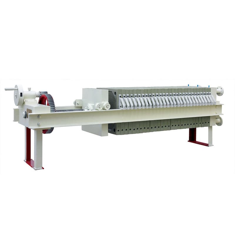
An industrial site's own treatment plant is almost never a single machine. It is a chain of units, each designed on the assumption that the one before it did its job, and dropping any link shifts the load onto its neighbours — usually onto the most expensive one. Here is the typical sequence, and what every unit in it is there for.
The order of units in the line
The classic on-site treatment layout looks like this:
- ✓Equalisation tank — evens out the flow and composition of the effluent.
- ✓Mechanical stage — a screen and a sieve remove coarse matter and fibre.
- ✓Reagent treatment — coagulant and flocculant convert dissolved and colloidal matter into a separable form.
- ✓Phase separation — a flotation unit or a settler removes what the reagents gathered into floc.
- ✓Polishing — brings the water to the values at which it is accepted for discharge or returned into circulation.
- ✓Sludge treatment — turns slurry into a cake that can be hauled away.
The order is not interchangeable. Reagents do not work on unequalised effluent. A flotation unit does not work without reagents. The polishing stage blinds within a day if suspended solids were poorly separated ahead of it. In fact the whole engineering of an on-site plant comes down to making sure each unit gets the feed it was designed for.
The outlet requirements are set not by the equipment but by the permit: the limit is assigned by the water utility or the local regulator, and it is specific to each site. That is why designing a line starts from which parameters have to be reduced, and to what values, at this particular place.
The equalisation tank — the unit most often dropped
An equalisation tank is simply a vessel with mixing, and that is precisely why it looks like the first candidate for saving money. It treats nothing, it takes up space and it costs money.
Here is what happens without it. Industrial effluent is uneven by nature: washdown comes at the end of the shift, the cook house dumps its batch inside a single hour, and at night the flow is close to zero. The machines further down the line are designed for a specific flow and a specific concentration. The DAF-20 flotation unit takes 15–20 m³/h, the DAF-50 takes 45–50 m³/h; that is a working range, not an "approximately". If a peak surge delivers twice the average hourly flow, then either the flotation unit is sized for the peak and stands underloaded three quarters of the day, or it chokes on the surge.
With reagents it is worse. The coagulant dose is selected for a specific contamination concentration. If the concentration triples, a dose set for the average turns out to be insufficient, no floc forms — and the whole surge passes straight through the line. An equalisation tank makes the composition predictable and the dose calculable.
Hence the rule: an equalisation tank is cheaper than any other way of coping with unevenness. It allows all the other equipment to be sized on the average hourly flow rather than on the peak.
Mechanical and reagent treatment
The mechanical stage — a screen and a sieve — removes what should never reach the machines at all: packaging, trimmings, fibre, sand. Its work is thankless and noticed only when it is absent: fibre winds around the flotation unit's scraper, sand settles in the settler's sludge hopper, coarse matter clogs the pump.
Reagent treatment is where effluents stop being alike. The coagulant removes the electric charge from fine suspended matter and the particles stick together into microfloc; the flocculant stitches microfloc into large, strong floc that can then be separated. The dose is selected by jar testing on the specific effluent, not from the reagent data sheet, and it is revised whenever the plant changes what it produces.
pH is corrected at the same point: coagulants work in a narrow range, and outside it the reagent is wasted. In practice this means that the reagent unit is at least two dosing stations, not one.
Flotation or settling
Phase separation is the point where the line splits into two options. The choice is determined by what exactly is in the effluent.
| DAF flotation unit | Lamella clarifier | |
|---|---|---|
| Principle | air is dissolved under pressure and, when the pressure is released, comes out as bubbles that lift the contaminants to the top | suspended solids settle under their own weight on a pack of plates inclined at 60° |
| What it removes | suspended solids, fats, oils, emulsions, fibre, petroleum products | dense settleable solids, metal hydroxides |
| Moving parts | pressure pump, mixers, scraper | none |
| Service | automatic, with remote monitoring | minimal, requires no specially trained operator |
| Capacity range | DAF-2.5 (2–2.5 m³/h) — DAF-100 (95–100 m³/h) | LC-1 (1 m³/h) — LC-120 (120 m³/h) |
Flotation takes the light and the emulsified — what gravity settling handles poorly. Hence its typical sites: meat and fish processing, dairy production, petrochemicals, the pulp and paper industry, food plants. The sludge here floats up and is removed by a stainless steel chain scraper; part of the treated water is returned to the pressure line so that air saturation stays stable. The coagulation and flocculation chambers of flotation units are built into the body together with the clarified water tank — the reagent unit partly ends up inside the machine.
A lamella clarifier takes what settles on its own. The inclined pack multiplies the settling area for the same footprint, so the machine takes up less room than a classic horizontal settler and requires less civil work. There are no moving parts inside — low power consumption and minimal service. Typical tasks are electroplating and production sites where the effluent carries copper, iron, zinc and nickel, mine water, effluent from dyeing and finishing, tanning, food and chemical plants, storm water, cooling tower blowdown, landfill leachate.
If the effluent contains both — fats and dense mineral solids — the stages are installed in series rather than one being chosen over the other.
Polishing and sludge are designed in from the start
Polishing is the last stage before discharge or return into circulation. Its make-up is dictated by the discharge permit and by where the water goes next: filtration, sorption, disinfection, and for return into the process, a membrane stage. There is no point designing it before the site requirements are known, but space for it is reserved from the start.
Sludge treatment is the unit most often put off "until later", and that is the most expensive mistake in a project. The reason is simple: everything the line removed from the water has not gone anywhere. Float sludge and settler sludge are a watery mass, and their volume is comparable with the flow the plant was built for in the first place. Without dewatering, what you haul away is water.
Dewatering options differ in operating mode:
- ✓The DS screw press works in flow-through mode and takes dilute sludge straight from the aeration tank or the settler, without a separate sludge thickener — which then need not be built at the plant. The range runs from DS-131 (about 6 kg of dry solids per hour at 1.00 % DS) to DS-404 (about 400 kg DS/h, on the order of 40 m³/h). The screw rotates slowly, and consumption of energy and wash water is low.
- ✓The belt filter press is also a flow-through machine: FP 1000A delivers 200–203 kg/h of dry solids, FP 2000A is designed for a water flow of 20.8 m³/h.
- ✓The CFP chamber filter press works in cycles: the plate pack is filled, then opened and the cake is discharged. Pressure filtration gives a cake of low moisture content and suits sludge that is viscous or very wet. CFP80 has a filtration area of 80 m² and a capacity of 1–2 t/h; CFP200 has 200 m² and 4–5 t/h.
Sludge is flocculated again before dewatering: the screw press takes pulp from a flocculation chamber. So a reagent unit is needed here too — one more reason to design sludge treatment together with the line rather than after it is commissioned.
What next
To size a line, collect four things: the average daily and peak effluent flow, an effluent analysis for suspended solids, fats, COD and metals, the discharge permit requirements for your site, and the space you have available. Assess separately where the cake will go — the choice of dewatering machine depends on it.
With these figures, look at industrial wastewater treatment: DAF flotation units, lamella clarifiers, screw presses and filter presses are selected for the flow and the nature of the effluent. If you do not have an effluent analysis yet, that is where to start: a line assembled without figures usually turns out either excessive or insufficient, and reworking it costs more than measuring.
